I have now got the ESP-12E forwarding the captured data over websockets/wifi to a little python server on a laptop and being recorded in a SQLite table, so far it has very little error handling at either end. I've never really been keen on python's use of whitespace for statement indentation, so switching between writing client code in C and server code in python does my head in.
Fairly obviously, the first byte of each packet indicates a packet type, some packet types are fixed length, others have a size in the header followed by a variable number of bytes. I've identified one packet type sent every 15 seconds which contains a unix timestamp and the instantaneous power reading in watts from the electricity meter.
I haven't managed to figure out any packets recording the consumption in kWh yet, no packets stand out as related to gas usage yet, but at this time of year the boiler only kicks in for a few minutes to top-up the hot water once or twice a day.
Finally some decent progress - after giving up on the FT220XB dongle because it could only do partial SPI slave communication, I encountered a similar issue with the ESP-12 module; the Arduino software library for SPIslave that I found last year has its own concept of the packet structure of a burst of data (send command, send address, send data, pause, receive data) which might be helpful if you're talking to an SPI flash ROM but it's not what I need, however looking at the source was very handy to understand the functions of the SPI hardware registers and it seems you can turn some or all of those elements off, but even at the hardware level the SPI interface still wants to enforce a scheme where master and slave take turns at reading or writing in e.g. 32bit or 32byte chunks.
So I decided that as the clock period of the bus I'm sniffing is only about 20µs i.e. 50kHz, and the ESP8266 CPU runs at 80MHz, there's plenty of time to just bit-bang it using some spare GPIO lines, so I now have a couple of interrupt driven routines watching for edges of the SELECT and CLOCK pins and shifting in bits from the DATA pin at the relevant times, then poking the bytes into a ring buffer.
The main loop of the program can can suck the data out of the ring buffer, more or less at its leisure as there are only one or two bursts of data each second. At the moment it just squirts it down a serial line to the laptop where I capture it with PuTTY, but it won't take much extra work so make the ESP-12 send the data over WiFi e.g. as UDP packets to a syslog server or something similar where I can timestamp each packet's arrival, or stick it into a SQL database.
The captured SPI data I receive matches exactly that which is decoded by the digital oscilloscope, and having it on the PC is much easier to look at a few KB at a time, rather than merely a handful of decoded bytes at a time.
Just to explain the formatting of that, though I capture data as bytes, I transfer them through the ring buffer as words, so I can use 'magic' values such as 0xFFFF to indicate boundaries in the stream which were transmitted within a single SELECT cycle on the SPI bus, and 0xBBBB to mark when my code first boots up, maybe I'll think of other useful hints to slip into the stream later such as 0xAAAA for a regular "still alive" message in case the RF module gets upset, the original connection between the two PCBs was only about 1cm of pins, at the moment it's about a foot of ribbon cable, clip-on probes, breadboard and jumper wires, the signals are noticably "fuzzy" but can still be read cleanly, though every now and then the main PCB complains it has lost communication with the meter and asks to be repositioned closer to it!
The eagle-eyed may spot that the packets beginning 01 3C 02 10 3C then have an incrementing byte following, obviously some type of counter, except that it wraps back from 0x77 to 0x01, what's so special about 119 I wonder? When the in-house display has been rebooted, it takes it a considerable time to build back up the historic data from the meters for the past hour/day/week/month/year, so that is probably the bulk of the repeating packets that the meter sends to the display, and I'm now seeing.
The electricity meter updates the instantaneous power consumption to the in-house display every 10-15 seconds, so I guess sitting there turning a fan heater on and off will easily allow discovering the packet types for that, and similarly the gas readings every 30 minutes to be fathomed out. Also the actual meter registers in kWh and m3 ought to be relatively easy to spot.
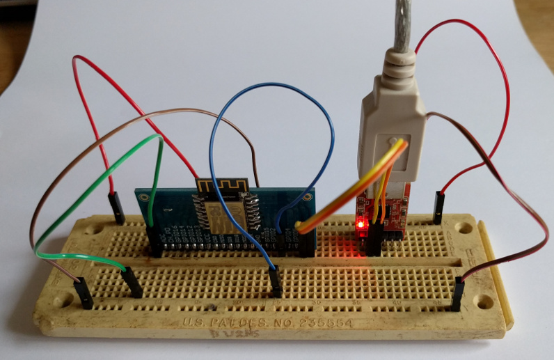
Another minor update - I'm no longer convinced the FT220XB dongle is suitable for use as a SPI slave, so I've purchased a couple of ESP-12F WiFi modules.
Soldered one to a breakout board, double-checked that my USB→TTL-RS232 adapter really does use 3.3V levels as the WiFi module is not 5V tolerant, and hooked it up to the laptop, the USB adapter can just about provide sufficient power to run the ESP-12F without a separate power supply (sometimes when resetting the ESP-12F it also resets the CP2102, but you can reconnect and it's all happy).
Using PuTTY and a couple of AT commands later this tiny board less than 1"x¾" is connected to my WiFi!
It might be nice to flash the Lua or MicroPython firmware to it as an interpreted prototyping environment but I can't see any libraries that allow either of those to use SPI slave mode. I have seen some native C code, so might have to roll my sleeves up, the aim being to snoop smartmeter data from the daughterboard over SPI and make it available as RESTful data using an embedded http server.
A minor update - I connected the FT220XB dongle, and tried a basic python program to send read commands and read bytes in a loop, I didn't get any data, in fact merely having the dongle connected between the main and daughter PCBs was preventing the IHD from receiving data from the meters, presumably there's an issue with loading or pull-up of the bus even though it should allow multiple slaves, everything recovers when the dongle is detached, so I'll have to have the scope and dongle attached at the same time to see what is happening to the signals on the SPI bus.
Several years ago I had smart meters fitted by e.on, the installation consists of Landis+Gyr (ex Ampy Automation) equipment, namely a Libra 310 gas meter, a 5236 electricity meter and a p350 ecometer in-house display.
Given that I previously had a Current Cost clamp meter, and had half-heartedly collected data from its serial port, I was a little disappointed to find that the IHD didn't have any serial or USB port to allow collecting data, I pondered whether the communication between the meters and the display might be ZigBee or Wireless M-Bus, I even considered buying an AMB8645 USB dongle to investigate, but the price put me off as I wasn't sure it was the correct protocol and I never looked much further at it.
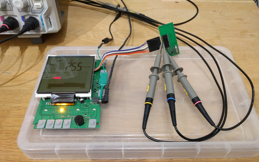
Having recently treated myself to a digital oscilloscope, I decided to open up the display unit and see if I could "sniff" any data from it. The display unit has a main circuit board with voltage regulator, LCD display, status LEDs, membrane switches and a beeper, it also has a daughter board connected by eight 0.1" header pins
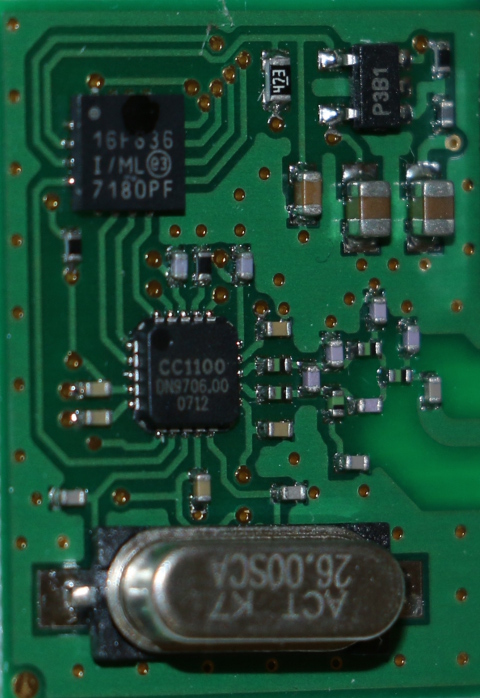
with a PIC16F636 microcontroller and a Texas Instruments CC1100 RF transceiver, some discrete components and PCB trace antenna. So I rigged up a ribbon cable extension to fit between the main and daughter boards and allow clipping the scope probes on, thankfully this didn't upset the communication between the boards, the IHD still receives meter readings OK.
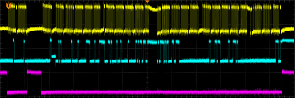
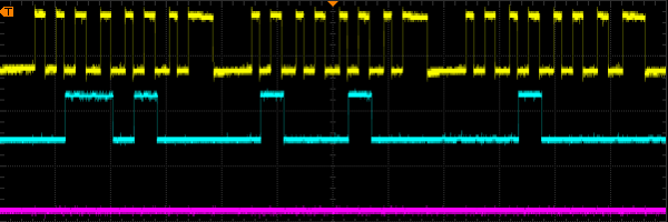
I soon tracked down a pair of data and clock pins that received regular pulse trains, initially I thought these were an I2C bus, but the bitstream wasn't correct for that (no 9th bit for ACK) so I probed a bit further and found a CS pin for an SPI bus, below is the same capture with different timebase settings ...
A sequence of two bytes followed by twenty three bytes, notice that some bytes are somewhat stretc-h-e-d.
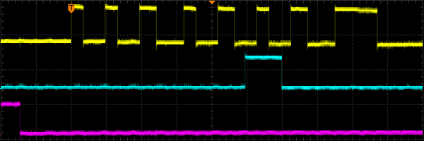
Zoomed in to three of those bytes.
Zoomed in further to a single byte, note the individual bit lengths are somewhat irregular, in particular the 8th bit is always longer than the others, I guess the PIC is busy doing other stuff?
The scope doesn't do a perfect job of decoding the SPI bus, for a start it will only decode a waveform if it sees the CS pin go low within the data that's on screen (rather than off to the left in the memory buffer) and sometimes if you slightly shift the horizontal offset then one or two data bits will "flip", but it lets me see periodic, non-random looking data with minor variations being received ...

The scope can dump the decoded data to a USB stick
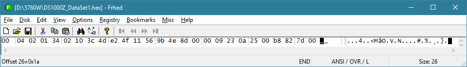
so it seems not to be encrypted and now I need to capture enough of it to work out the data fields within it.
I have a TUMPA-lite interface which I hoped to use to log the data with a laptop, but it seems the FT232H chip can only act as an SPI master so I haven't tried anything with it, instead I've purchased an FT220XB USB dongle which is "nearly" an SPI slave, close enough that I hope it will cope with the signals coming from the daughter board, if I get nowhere with that, I'll probably try a Bus Pirate.
Previously I've used Python and the Adafruit GPIO library to control the FT232H for driving some RGB pixel LEDs (I've got some changes to their code I ought to offer back to them) I'll try to use the same to read the data using the FT220.